Class Diagram
The Class Diagram is at the heart of UML. It is based on the principles of object orientation (abstraction, encapsulation, inheritance, etc.) and can be used in all phases of a project thanks to its versatility. In the analysis phase, it appears as a domain model and attempts to represent an image of reality. In the design phase, it is used to model data structures and the software, and in the implementation phase it is used to generate source code.

Class diagrams are used to model classes and relations between classes. There are roughly three types of relationships. The simplest and most general variant is the association. A second modelable relationship is the inclusion of a class in a second class, the so-called container class. Such relationships are called aggregation or composition. A third possibility is specialization or generalization.
As a class must model the structure and behavior of objects created by this class, these can be provided with methods and attributes. It is also possible to model base classes and interfaces using stereotypes. Template classes can be implemented in some programming languages. The UML represents such classes in the class diagram as parameterizable classes.
Class
A class describes a set of instances that have the same characteristics, assurances and semantics.
Classes are represented by rectangles that either only contain the name of the class or also contain attributes and operations. These three sections (compartments) – class name, attributes, operations – are each separated by a horizontal line. Class names usually begin with a capital letter and are usually nouns in the singular (collection classes and similar may be in the plural).
The attributes of a class are listed with at least their name and can also contain information about their type, an initial value, property values and assurances. Methods are also listed with at least their name, plus possible parameters, their type and initial values, as well as any property values and assurances.

Fig. 30: Sample Class
Visibility range
The visibility range (scope) of the class elements is marked with a sign in front of the name. If an element is publicly visible, the + sign is placed in front of the name. Private elements are preceded by the – sign. The # character in front of the name means that the class element is marked with the protected access attribute. Protected means an extension of private – child classes inherit attributes that are marked as protected.
~ in front of the name means package – a restriction of public; not unlimited public visibility, but limited to the package.
Abstract class
Instances of an abstract class are never created. It is deliberately incomplete and therefore forms the basis for further subclasses that can have instances. An abstract class is displayed like a normal class, but the class name is put in italics.

Fig. 31: Example Stereotype
Stereotypes
Stereotypes can be used to identify abstract classes, for example. The stereotype appears above the class name in French quotation marks “ ”. Stereotypes can also be made visible by using different colors or by writing the name of the class in italics.
Parameterisable classes
Parameterisable classes are a special type of class. The type of attributes contained in these classes is not yet defined. They are only defined when an object of these classes is instantiated. The graphical representation is modified for such classes. The rectangle for the class is given a second rectangle with a border at the top, which contains the variable type.
Object
Objects are the concrete, acting units of an object-orientated application. They are created in the memory according to a blueprint, the class definition. Each object has its own identity. An object has a certain behaviour that is determined by its methods. Two objects of the same class have the same behaviour. Objects also have attributes that are the same for objects of the same class. The state of an object is determined by the values stored in the attributes. Therefore, two objects of the same class are identical if the values in the attributes match.

Fig. 33: Sample Objects
In the diagram, objects are drawn with a rectangle in the same way as the classes. The name is underlined to distinguish them from the classes. The class name is added to the name of the object after a colon. If the specific object name has no meaning for the case to be modelled, it can also be omitted. Only a colon and the class name are then displayed. As the methods are of no interest in the object representation, they are not specified.
Attributes
An attribute is a (data) element that is contained equally in each object of a class and is represented by each object with an individual value.
Unlike in UML 1.x, in UML 2.0 and later there is no longer a strict distinction between attributes and association ends. This means that the representation as an attribute in a class or as a navigable association is the same.
Each attribute is described at least by its name. In addition, a type, visibility, initial value, etc. can be defined. The complete syntax is as follows
[Visibility][/]Name[:Type][Multiplicity][=initial value]
Methods (operations)
A class must have a method for each message it receives. A class makes functionality available to other classes via a method. The objects installed from the classes communicate with each other via messages, i.e. method calls, and thus achieve coordination of their behaviour. Objects and their communication via method calls are shown in the group of interaction diagrams.
Relations
There are four different types of relationships between classes, with generalisation being a special form, while the other three – association, aggregation and composition – are very similar.
Association
The association represents the communication between two classes in the diagram. The classes are connected with a simple line. A directed association can be modelled using an arrow.
Each association can be given a name that describes the relationship in more detail. The name can also be given a reading direction – a small filled triangle. This direction only refers to the name and has no relation to the navigability of the association.
On each side of the association, role names can be used to describe in more detail the role of the respective objects in the relationship. The roles are the names of the properties (attributes) that belong to the association or one of the participating classes.
Associations are usually realised in programming languages by assigning corresponding attributes to the classes involved.
A role therefore represents a property. In addition to role names, visibility information can also be added to each side of the association. For example, if an association end is declared as private (-), the object itself, i.e. the operations of the object, can use the association, but neighbouring classes are not granted access.
A directed association is noted like a normal association, but it has an open arrowhead on the side of the class that can be navigated to, i.e. in the direction of navigation.
However, multiplicity and role name can theoretically also be noted on the side that cannot be navigated to. They then denote a property that does not belong to a class, but to the association.

Fig. 34: Association and composition with all details
In the example, the ‘Customer’ class would receive an attribute ‘account’ as a reference to an object of the Customer account class and the Customer account class would receive a private attribute ‘bpos’ with a collection object (collection or subclass thereof) that references the booking item objects.
A lot of modelling tools use the role names of the relationship for the corresponding automatically generated attributes; role names also correspond formally with the corresponding attributes in UML. Association with navigability is an alternative notation to the attribute representation in the associated class.

Fig. 35: Associations
These relationships are read as follows:
- An event has a
- A seating plan is a venue
The arrow indicates that communication predominantly originates from the seating plan (during implementation, the class therefore receives a reference to the venue).
The cardinalities are read before the target class.
Multiplicity
In UML, the term multiplicity is used to describe the number of possible values. Multiplicity is described by a minimum value and a maximum value, e.g. 3..7. If the minimum value is equal to the maximum value, the lower or upper limit can be omitted. Instead of 3..3, only 3 is then written. If the lower limit is 0, this means that the relationship is optional.
In UML, the term cardinality is also used to describe the number of concrete values.

Fig. 36: Multiplicity vs. cardinality
The term cardinality originally has its roots in data modelling, where it has the same meaning as multiplicity in UML. In UML, both terms are used and thus a finer distinction is made between possible values and actual values. Cardinality describes the concrete number of associated objects in the object model, for example.
Association class
However, classes can also be related to each other on a combinatorial basis. If we look at the relationships between customer, account and ATM card, it turns out that an ATM card exists for a combination of a customer and an account, which is completely different from associating the card with the customer and account directly. The UML provides the notation association class for this:

Fig. 37: Association class

Fig. 38: Association node (n-ary association)
A special feature of the association class is that there can only be one instance of the associated class per reference. In the example, there can only be one instance of ATM card for a combination of customer and account.
If several classes are involved, the association node (n-ary association) is used.
The n-ary association has its origins in data modelling (entity relationship models) and is used in UML with identical semantics. All classes involved in the association form a unit. In the example, this means that (flight ticket, date, flight, passenger) form a unit and have one meaning as a whole, i.e. participation in a specific flight. The meaning is usually expressed in the name of the association (hash). The meaning is usually expressed in the name of the association (hash).
An important aspect of the n-ary association is setting the multiplicities, i.e. which combinations of object values are valid. To be able to set the multiplicities correctly, think of a multiplicity of 1 for n-1 elements and set the multiplicity of the nth element.
For example: A passenger has exactly one flight ticket for a flight on one date. If it is possible for the passenger to have several tickets for the same flight on the same date, the multiplicity for flight ticket must be greater than 1 (e.g. *).

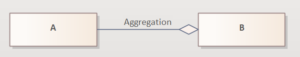
Fig. 39: Notation Aggregation
Aggregation
An aggregation is an association, extended by the semantically non-binding comment that the classes involved do not have an equivalent relationship, but represent a ‘part of’ relationship. An aggregation is intended to describe how something as a whole is logically composed of its parts.
Like an association, an aggregation is represented as a line between two classes and is also marked with a small diamond. The diamond is on the side of the aggregate, i.e. the whole. In a way, it symbolises the container object in which the individual parts are collected. All other association notation conventions apply.
The example of company-department-employee shows that a part (department) can also be an aggregate at the same time.

Fig. 40: Sample Aggregation
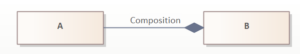
Composition
A composition is a strict form of aggregation in which the parts are existentially dependent on the whole. It describes how a whole is made up of individual parts. Like the aggregation, the composition is drawn as a line between two classes and is provided with a small diamond on the side of the whole. In contrast to the aggregation, however, the diamond is filled in.
If a class is defined as part of several compositions, as for example in the following illustration, then this means that both cars and boats have an engine, but a concrete engine object can only ever belong to either a car or a boat.
The key feature of a composition is that the aggregated parts are never shared with other objects. This can also be described in the diagram using XOR constraints.

Fig. 41: Aggregation and Composition

Fig. 42: Sample Composition
If the multiplicity for parts (engine) starts from zero (0..*), then the whole can also exist without parts, or contain any number of parts. If the multiplicity of the whole (car/boat) is zero to one (0..1), then the part can also exist without the whole, but as soon as the part belongs to the whole, it is no longer separated and an existence-dependent relationship arises.
Existence-dependent means that the part cannot exist without its whole and if the whole is destroyed, all its parts must also be destroyed.
In the illustration, an aggregation is modelled between the event plan class and the seating plan class. A composition is defined between the seating plan and seat classes. There is therefore no seating plan object without a seat. The relationships are read as follows:

Fig. 43: Sample Aggregation and Composition
- A seating plan has any number of seats, but at least one.
- A seat belongs to exactly one seating plan
- Each seating plan belongs to one event
- An event can have any number of seating plans
- The seating plan could also be assigned to another event (aggregation), but must always have an event.
- The seat belongs to a seating plan, this relationship cannot be changed (composition)
Generalisation / Specialisation
A generalisation is a relationship between a general and a special class, whereby the more special class can add further characteristics and behaves compatibly with the general class.
In generalisation or specialisation, characteristics are structured hierarchically, i.e. characteristics of more general significance are assigned to more general elements and more specific characteristics are assigned to elements that are subordinate to the more general ones. The characteristics of the superior elements are passed on to the corresponding sub-elements, i.e. inherited. A sub-element therefore has the characteristics specified in it as well as the characteristics of its super-elements. Sub-elements inherit all the characteristics of their super-elements and can extend or overwrite them with additional ones.

Fig. 44: Sample inheritance
This form is used to model hierarchical inheritance trees. Inheritance trees are an important design element when modelling software architectures. In the illustration, for example, it is modelled that events can be in-house or guest events.
Dependencies
A dependency is a relationship between one (or more) source element(s) and one (or more) target element(s).
The target elements are required for the specification or implementation of the source elements. A dependency is represented by a dashed arrow, with the arrow pointing from the dependent element to the independent element. In addition, the type of dependency can be specified in more detail using a keyword or stereotype.
As the source element in a dependency relationship requires the target element for its specification or implementation, it is incomplete without the element.
Dependencies can have different causes. Some examples of this are
- One package is dependent on another. The cause may be, for example, that a class in one package is dependent on a class in the other package.
- A class uses a specific interface of another If the interface offered is changed, changes are also required in the class using the interface.
- An operation is dependent on a class, for example the class in an operation parameter A change in the class of the parameter may require a change in the operation.
| Stereotypes | Meaning |
|---|---|
| «call» | Stereotype of a usage relationship: The call relationship is defined from one operation to another operation and specifies that the source operation calls the target operation. A class can also be selected as the source element. This then means that the class contains an operation that calls the target operation. |
| «create» | Stereotype to usage relationship (Usage): The dependent element creates copies of the independent element. The create relationship is defined between classes. |
| «derive» | Stereotype to abstraction relationship (Abstraction): The dependent element is derived from the independent element. |
| «instantiate» | Stereotype for usage relationship (Usage): The dependent element creates copies of the independent element. The relationship is defined between classes. |
| «permit» | Keyword for authorisation relationship (Permission): The dependent element has permission to use private properties of the independent element. |
| «realize» | Keyword for realisation relationship (Realisation): The dependent element implements the independent element, for example an interface or an abstract element or an element must implement a requirement. |
| «refine» | Stereotype for abstraction relationship (Abstraction): The dependent element is at a more concrete semantic level than the independent element. |
| «trace» | Stereotype to abstraction relationship (Abstraction): The dependent element leads to the independent element in order to be able to trace semantic dependencies, for example from a class to a requirement or from a use case to a class. Often also used between test case and tested element. |
| «use» | Keyword for usage relationship: The dependent element uses the independent element for its implementation. |
The abstraction relationship (abstraction) is a special dependency relationship between model elements on different abstraction levels. The relationship is noted like a dependency relationship. However, they cannot be confused, as the abstraction is always used together with a stereotype. The UML defines the standard stereotypes ‘de- rive’, ‘trace’ and ‘refine’.
An abstraction relationship always includes a mapping specification of how the elements involved relate to each other (mapping). The specification can be formal or informal. Despite the direction of the arrow, an abstraction relationship can also be bidirectional depending on the stereotype and mapping rule, e.g. often the ‘trace’ relationship.
A special abstraction relationship is the realisation relation. It is a relationship between an implementation and its specification element.
The substitution relationship (substitution) is a special realisation relationship. It specifies that instances of the independent element can be substituted by instances of the dependent element at runtime, e.g. because the elements implement the same interfaces.
The usage relationship is a special dependency relationship. The difference to the dependency relationship is that the dependency is only limited to the implementation and does not apply to the specification. This means that the dependent element requires the independent element for its implementation. There can therefore be no usage relationships between interfaces, but there can be a dependency relationship.
The authorisation relationship (permission) is a special dependency relationship that grants the dependent element access rights to the independent element.
Interfaces
Interfaces are special classes that specify a selected part of the externally visible behaviour of model elements (mainly classes and components) with a set of characteristics (features).
The implementation relationship is a special realisation relationship between a class and an interface. The class implements the characteristics specified in the interface.
Interfaces are notated like classes, but have the keyword ‘interface’.
A distinction is made between provided and required interfaces. A provided interface is offered by a model element and can be used by others. A required interface is an interface that is requested by another model element.
Interfaces specify not only operations, but also attributes. Accordingly, interfaces may also have associations to other interfaces or classes.
Classes that want to implement an interface must implement all operations defined in the associated interface. With regard to the attributes defined in the interface, the implementing class must behave as if it owns the attributes. In the simplest case, it actually implements the attributes. However, it is also sufficient to only offer the corresponding get() and set() methods, for example.
A class can implement several interfaces and also contain further properties or, in other words: an interface generally describes a subset of the operations and attributes of a class.
There is a special realisation relationship between the implementing class and the interface, the implementation relation (keyword ‘realise’).

Fig. 45: Sample Interface
It does not appear clearly from the current specification whether the dashed arrow with the keyword ‘realize’ is used for the implementation relationship or whether the dashed generalisation relationship is used as in UML 1.x. We assume the latter here, as this variant is also much more suitable for practical work. We assume the latter here, as this variant is also much more suitable for practical work.
The implementation relationship is noted with a special arrow. The other way to represent the implementation of an interface is a small, unfilled circle connected by a line to the class that provides the interface. This is intended to symbolise a connector. The name of the interface is shown next to it; it corresponds to the name of the associated interface.

Fig. 46: Notation of the provided interface
With arrow notation, it is possible to read the operations and attributes required by the interface. With short notation, you cannot see the operations and attributes required by the interface, only the name of the interface.
For a requested interface, the requesting element has a usage relationship to the interface. The existing short notation for this is a semicircle on the handle. This is intended to symbolise a socket.

Fig. 47: Notation of the requested interface

Fig. 48: Notation options for interfaces (usage and delivery)
The providing and requesting of an interface can also be represented by the combination of the two short notations by inserting the plug into the socket.
However, be warned about the last representation: In contrast to the symbols for the provided interface and used interface, the ‘assembly’ belongs to the connector category. Consistent modelling with an instance classifier reference to the interface description will not be possible. You should therefore avoid this notation.
As interfaces are special classes, all corresponding rules apply. For example, generalisation is possible.

Fig. 49: Extension of interfaces

Fig. 50: Example of implementing interfaces
The illustration shows that the ‘Opel Astra’ class implements the ‘Car’ interface. The Auto interface requires four operations: steer(), shift(), brake() and accelerate() as well as two attributes ‘speed’ and ‘driving direction’. The ‘Opel Astra’ class fulfils the requirements for this interface, as it has the four required operations and two attributes, among other things.
| Name/Symbol | Usage |
|---|---|
 | A class is shown in the diagram with a rectangle in which the name of the class is displayed. The class symbol can be extended with an area for displaying the attributes and methods. For parameterisable classes, the class symbol is extended with a rectangle containing the name of the parameter. |
 | Objects are displayed with a rectangle in which the name and class of the object are underlined. Both are separated by a colon. The class name can be omitted if the object can also be categorised without a class name. An anonymous object (without a name) is only indicated with a colon and the class name. |
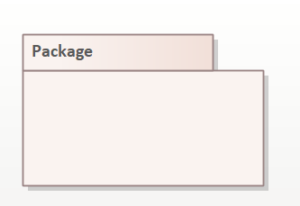 | Packages contain several classes that have been grouped together for a specific task. The graphic for a package symbolises an index card containing the package name. |
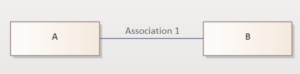 | If two classes are related, this is shown by the connection between the two classes with a solid line. |
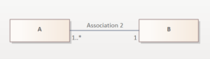 | The line can indicate the cardinality near the class symbol. |
| The name of the relationship and the role can also be specified on the line (roles: accused, accuser; relationship name: accuses). | |
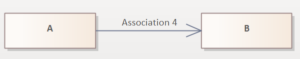 | You can use an arrow to indicate the primary direction of communication. (Navigation) |
 | The aggregation is represented by a line with a diamond symbol at one end pointing to the class of the container (class B can manage objects of class A). The diamond symbol is not filled. The roles, cardinality and primary direction of communication are specified in the same way as for the association. |
 | In contrast to aggregation, composition is shown with a filled diamond. The other symbols correspond to those of the aggregation. |
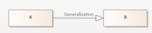 | The symbol is an arrow that points to the base class and connects it with the derived class. The arrow is not filled (class A inherits from class B). |
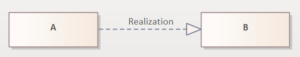 | If a class implements an interface, the connection is shown with an arrow and a broken line. |
Example
In a ticket system for a theatre, all of the theatre’s plays are managed via an event schedule. The event schedule class is linked to the theatre schedule class via a composition. This means that the Event plan class can manage objects of the seating plan class. Each seating plan contains the theatre’s seats and these are sold via the seating plan.
The seating plan class manages objects of the place class via another composition. Navigation is directed towards the place class. The seating plan class communicates with the Event class, in which the performance data is outsourced, e.g. date and time.
The venue details, e.g. the name and address, have been outsourced to the venue class. Navigation takes place from the seating plan class.

Fig. 51: Sample Class Diagram