Use Case Diagram
Use Case diagrams provide a very good overview of the entire system on a highly abstract level. They describe functionality - services and activities to be performed - from the view of the user, and act as the interfaces to the environment. It is important to consider that Use Case diagrams themselves cannot describe behaviors and processes, but rather only the associations between a number of use cases and the involved actors. These may be used for the analysis and management of requirements. Likewise, no order of appearance of described activities/services is shown. A major advantage of the Use Case diagram lies in the structuring of task assignment; subsequently – what will be delivered by the system? - all further specifications can be hierarchically ordered and extended below as Sub Use Cases or other model parts. Help in securing projects by quickly determining job scope and evaluating cost is another advantage. Use Cases provide an overview of function on top of the documentation of the planned system.
This type of diagram describes the goals of the user and is especially good for analyzing the functional requirements placed on a system. It is comprised of only a few yet very intuitive elements and, due to its simplicity, is very well suited for communication between principal (customer) and agent (sub-contractor). Both parties can develop a common view of the system, thereby helping to avoid misunderstandings concerning operational scope in a timely manner.
A Use Case diagram is the graphical representation of the Use Cases and their relation with the environment (interacting users) and their relations with each other. Important information is stored within the textual meta-content of the Use Cases or within diagrams behind, providing detailed information for each one. Use Cases may contain: A self-explaining name, an explanation of the name (note), pre- and post-constraints and a scenario describing the necessary steps to fulfill the functionality/service.
By collecting all important functional requirements by Use Cases it’s also possible to plan and discuss all necessary acceptance test cases; test cases for the functionality, for each constraint, for the assigned non-functional requirements and for the included scenarios.
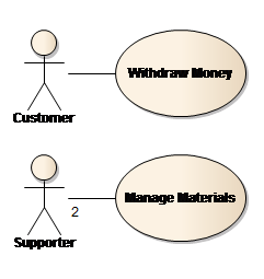
This Use Case diagram shows two use cases and their associated actors. When read from top to bottom, these two use cases suggest a particular order, but in UML this is neither given nor intended. The diagram merely describes what use cases there are and the involved parties. Process flow and order can be described textually within the scenario or later on within additional behavioral models by using activity, state or sequence diagrams.
Actors
In a use case diagram, all parties (stakeholders) involved in a procedure are portrayed with the help of Actors. An Actor is defined as a role outside of the corresponding use case system, and which interacts with the system within the context of the use case. Actors can be persons who use the system or external systems which access the system. They have demands and interests on the system, and are accordingly interested in the results. There can also be events which are triggered without the involved parties (e.g. time events).
An Actor describes a role, which may be replaced by a discrete person (or system) when realized. For example the role “Customer” can be replaced by any person being a customer of the bank. In special cases, when the role cannot be replaced by a discrete person (or system), it has to be marked as Abstract to express that the actor is a generic role. To qualify an UML element as an abstract element, the name of the element will be shown in italic in an UML diagram.
Stereotypes may be used to categorize actors like sensors, timers, actuators, environmental influence, etc.
The following illustration shows different notations of an actor. UML provides the stick figure as the Actor symbol. The role name of the actor is placed above or below the figure. It is possible to use any user-specific symbol. The block located to the right is the node symbol from the deployment diagram type. The use of a block-type symbol (or similar) to indicate an external system is widespread, as a stick figure usually indicates a human user.

Use Case
A use case specifies a number of actions executed by a system and which lead to a result which is usually important to an actor or stakeholder. Use cases are the activities which one names when describing a process. As an example: for a ticket system, that would be the buying, reserving or cancelling of tickets.
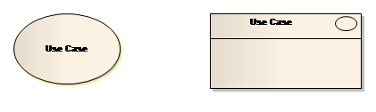
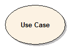
The following illustration shows various forms of notation of use cases. The illustration on the left is standard notation. It is also possible to note the names of the use cases under the ellipse. The advantage here is that the size of the ellipse must no longer scale to the name of the use case. Interestingly, unlike actor notation, placing the name above the ellipse for use cases is not practiced in UML.
System (System Boundary)
System is not a strictly UML modeling element. System can be understood as the context of the use case in which the use cases of specific actions are executed. System can be a class or a component which represents the entire application. The system is represented by one or more system frames (boundaries); Use cases – services and activities - to be performed by the system are shown in the system frame.
Attention: To draw actors within a boundary will be incorrect!
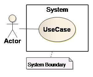
Fig. 8 System
Relationships
Use cases and actors have a certain relationship with one another. Relationships are modeled with lines. Linking actors and use cases in this way means that both communicate with each other. An actor is linked to use cases using simple association. This indicates an interaction with the system belonging to the use case, and in the context of that use case. Relations can carry additional information, if needed.
It’s possible to add multiplicity1; a multiplicity on the use case side indicates how often this use case can be executed by this actor at the same time. Without a writing, multiplicity will be 0..1 by default. On actors side a written multiplicity means the number of actors of the given role to be involved when interacting with the use case. Without a writing, multiplicity on actors side will be 1..1, which can be written as 1 with same meaning.
It is not common for one to use navigable relations; however, these are allowed. These do not represent a specific direction of data flow – as they are usually interpreted – but rather indicate the initiator of the communication between actor and system.
Indicating a navigable association (arrow to or from an Actor), even more semantics with a use case can be expressed. A directed association describes which part is the active and which is the passive. When an actor navigates to a use case, then the Actor is the active party and initiates the use case. Vice versa, in navigation from use case to actor, the actor is passive and will be required and requested by the use case to participate.
The following example expresses that the Customer triggers the use case withdraw money, but once a time. To process withdraw money the Bank-Server is needed (it’s passive). While the Bank-Server can be involved in any number of withdraw money use cases at the same time, the Customer can be involved only once at the same time.
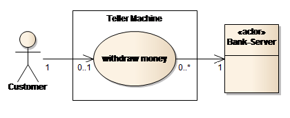
Fig. 9 Multiplicity and active/passive actors
[1] The multiplicity is a time-dependent value with a lower and an upper border, written as x..y , indicating how many instances of the element are needed. Multiplicity describes the amount of possible instances, cardinality on the other hand a concrete amount.
Use Case Relationships
Use cases can also be reliant on one another
- With the "Include" relationship, a use case is bundled into and is a logical part of another use case. It represents a compulsory relationship and is therefore often referred to as "must-relationship".
- With the "Extend" relationship, however, one can also specify that a use case is to be extended under certain conditions and on another specific point (the so-called extension point). It represents an optional relationship and is therefore often referred to as "can-relationship".
- Use cases can also be generalized, whereby the general rules apply. Use cases can also be abstract (italics) and first be made clear via sub-use-cases (specialized Use Cases).
Include Relationship
A part of a use case which appears in the same identical form in other use cases may be transferred to its own use case and re-integrated universally via an Include relationship in order to avoid the redundant specification of these identical parts. Unlike the Generalization relationship, when utilizing the Include relationship no characteristics are passed on.
The Include relationship is illustrated by a dashed arrow with open point in the direction of the use case to be included. The key word "include" is noted for the arrow. An actor must not necessarily be linked to the integrated use case.
Integrated use cases are often provided with the stereotype "secondary". This is not UML-Standard, but it is in common use since they are normal incomplete (use case fragments) and must be distinguished from the primary (normal) use cases.
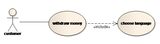
Fig. 10: Example of "include" relationship
Within a use case diagram an include relation specifies that the use case always uses the second one. The timing of the usage is not expressed by the diagram itself, it may be described within the use case scenario or by a behavioral diagram describing this use case in detail.
Hint: Please pay attention to include only use cases of the same specification level.
Functionality needed several times should be modeled as use case once and can be used by others with relations any time needed.
Extend Relationship
If a part of the tasks are transferred from one circumstance to another, this is modeled in its own use case. The arrow is given the stereotype "extend". The Extend relationship points to the use case to be extended, and starts from that use case which describes the extension's behavior.
This has been defined by the inventors of UML, they preferred to have "extend" instead of "extended by".
A use case can define any number of extension points. A condition on the Extend relationship is optional. If no condition is indicated, the extension will always occur. It is not absolutely necessary for an actor to be linked to the extended use case.

Fig. 11: Example "extend" relationship
The extended use case may be described more detailed by using extension points (Fig. 12). An extension point describes the event activating the extension. An use case may define several extension points. In addition to an extension point you may define conditions. If you don't specify a condition, the extension will be executed always. The example shows the use case withdraw money in rectangle notation1. The use case contains two extension points2. Both extension points are describing the sufficient trigger (logical "or", one of them is enough). But there is also a condition paper available. At least one extension point for a must become true AND the condition paper available must be valid to execute print receipt!
As in the case of an include the diagram does not specify the timing circumstances. It may be found within the scenario(s) of the use case or in behavioral diagrams describing the use case in detail.
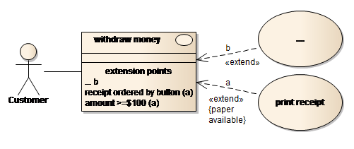
Fig. 12: Example "extend" with extension points and condition
[1] right click on element | Advanced | Use Rectangle Notation
[2] right click on element | Advanced | Edit Extension Points...
Specialization (Generalization)
Another relationship is "Specialize". A use case (or an actor) stems from a generalized use case (or actor) and specializes it. For example, saving for the actual distribution channel, a sale at the box office is similar to a sale via the Internet. It is possible to create a general use case, "sales", and in specializing this use case to include the altered handling steps which occur due to the different distribution channels. This general use case is thereby assigned proxies for the various roles assumed by it. The same concept applies to actors.
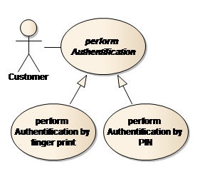
Fig. 13: Generalisation of Use Cases
Generalizations will be used for generic or abstract descriptions of functions too. The use case perform Authentification in the right sided figure is an abstract1 one and will not be performed itself. The two use cases perform Authentification by finger print and perform Authentification by PIN are two concrete variants of the generic Use Case. The perform Authentification may be used as a "placeholder" to stress that customers will have to identify themselves by choosing one of the variants. The abstract use case perform Authentification contains a generic description, what authentification has to provide, while the other use cases describe the deviations for the specific variant.
An actor describes a role, which may be defined arbitrarily abstract. For example a customer of any bank may use withdraw money. If the bank operating the teller machine is the borrower's bank, the customer may deposit money too.
This may be modeled by an additional actor Customer of TM-Operating Bank. Due to the fact, that this customer is also a "standard" customer, he is allowed to use everything that Customer is allowed to use - withdraw money.
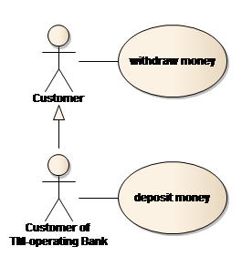
Fig. 14: Generalisation of Actors
In the diagram these circumstances are expressed by the generalization between Customer of TM-operating Bank and Customer. By this he becomes a Customer additionally (generalization is also named "is-a"), and he/she inherits withdraw money by this. On the other hand, Customer is not allowed to run the use case deposit money.
Hint: The opening triangle at the side of the generalist was chosen as symbol to indicate that the specialist has more functionality/capability, exceeding the functionality/capability of the generalist.
[1] select the element and within the window Properties set Abstract to True in the section Advanced
Descriptions and Notes
For all use cases and actors, UML allows descriptions to be added in the form of verbal and structured phrases. Due to their complexity, these are not suitable for display in diagrams. You can therefore add notes to the diagrams which refer to key design concepts. Notes are displayed as a square, the upper-right corner of which is folded in. A dashed line establishes the link between the note and element to be explained.
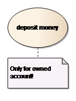
Fig. 15: Notes in Diagrams
To avoid parallel, conflicting comments - in diagram and within the element - you may put a reference to element content1 for the note in the diagram.
[1] select the element | Add | Note | OK (leave empty); right click on connector Link this Note to an Element Feature...
Graphical Elements
The following table lists the symbols used in modelling a use case diagram:
Name/Symbol | Usage |
Use Case | A use case is illustrated as an ellipse containing the name of the use case. The name of the use case is typically formed by a noun and verb whereby the object to be manipulated and the activity to be carried out are described in a clear and concise manner. |
Actor | A use case is triggered by an actor. Its illustration depicts a stick figure. Actors may also be placed within a square with the stereotype «Actor» placed above the name of that actor. |
Use
| When an actor has triggered a use case, that actor has formed a relationship with that use case. This relationship is shown by a line connecting the use case and the actor. |
Extend
| When a use case is extended by another under a specific condition, this relationship is indicated by connecting the use cases with an arrow labeled with the «extend» stereotype. The arrow points to the use case which is being extended. |
Include
| If one use case is contained within, and is therefore a key component of, a second, then both use cases are linked by an arrow labeled with the «include» stereotype. The arrow points to the contained use case. |
Generalization
| This relationship can be modeled between actors and use cases, and means that a use case or an actor is being specialized. The arrow points to the actor or the specialized use case. |
Note Note Link | Notes are diagram elements which are applied to other modelling elements. They contain information which provides a better understanding of the model, and are connected to the element by a dashed line. |

Example
A customer wishes to withdraw money from an automatic teller with a bank card. The actor named customer plays this role and is the generalization for own bank customer and third-party bank customer. The specialized actors communicate via the role of the customer with the identify card use case which proceeds equally for both types of customer. This use case contains the use case check account and PIN, whereby the right of the customer to use the card is assessed. If an incorrect PIN has been repeatedly entered, the card is withdrawn. To model this, the use case identify card is extended by the use case impound card. This is executed only under the condition that the customer repeatedly entered the incorrect PIN.
Both actors, own bank customer and third-party bank customer, communicate directly (and not via the role of customer) with the use case pay out. This procedure varies between these two types of customer; i.e. the highest withdrawal amount and/or fees per transaction can vary.
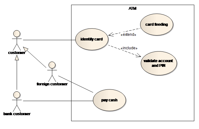
Fig. 16: Example of a Use Case Diagram